1. INTRODUCTION
Interesting properties such as high chemical resistance, high heat resistance, high electrical isolation, biocompatibility, large optical transition range and low optical absorption are desired from the device material. In MEMS devices fabrication, after silicon, glass is the second most widely used material.
2. GLASS ETCHING TECHNIQUES
There are three major groups of techniques used for glass etching: mechanical, dry and wet.
Mechanical methods include traditional drilling with diamond tipped drill bits, ultrasonic drilling [10], electrochemical discharge [11] or powder blasting [12, 13]. These methods are commonly use for performing etching through the glass wafer. However, smooth surfaces cannot be generated using such methods.
Dry etching techniques include plasma and laser etching of glass. Ronggui and Righini in [14] reported the first etching of glass in plasma with an optimal etching rate of 10 nm/min. Better results are reported using Deep RIE in ICP systems [15] using SF6 as gas and electroplated Ni (20 µm-thick) as masking layer. We also reported in [16] etching of pillars in an ICP reactor using C4F8 chemistry and 40 µm-thick bulk silicon as masking layer. The main advantage of this technique is the opportunity to generate structures with high aspect ratio, or microchannels with vertical walls. The disadvantages of plasma etching consist of relatively low etching rate (0.5-0.6 µm/min) which is halved by the cleaning process of the equipment required usually after each 10 µm depth etch. The rough surface generated (high energy sputter etching process) is another disadvantage of the process.
3. INFLUENCE OF GLASS COMPOSITION
These insoluble products are deposited on the generated surfaces and act as masking layers. As a result, after etching, the surface becomes rough and, in time, the etching rate decreases. For Hoya SD2 a large amount of Al2O3– (about 20%) is presented [28] while in the composition of soda lime, CaO (8.8%), MgO (4%) can be found [29]. In the composition of Corning 7740 the amount of insoluble products is only 2% (Al2O3) [29]. For this reason wet deep etching of glass is recommended to be performed on glasses with low concentration of oxides that give insoluble products in HF. This is why in our experiments we focus more on Pyrex glass (Corning7740).
4. ETCH RATES
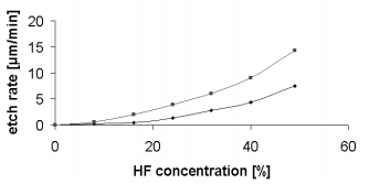
The etch rate is a characteristic for each type of glass, especially due to different oxides and different composition used during fabrication. For the HFbased etching solution the etch rate is determined by the concentration of HF enchants. To achieve a high etch rate, a standard concentration of 49% should be used. Figure 2 presents the influence of HF concentration on the etch rate for Corning 7740 Pyrex glass. It should be noted that by increasing the HF concentration from 40% to 49% a rapid increase of etch rate of 50-60% can be achieved (4.4 µm/min to 7.6 µm/min for non-annealed glass). At the same time no major difference in the resistance of mask in the etchant was observed.

Fig2
Other methods tested for increasing the etch rate, were: warming the solution at 50OC and using ultrasonic for agitation. The first method was tested in a sealed Teflon container warmed in hot water at the above-mentioned temperature. The increasing of etch rate was significant (about twice). However, this method is not recommended for safety reasons. By applying ultrasonic agitation we also noticed increases of the etch rate, but the resistance of the masking layer in the etchant is drastically reduced.
The pinholes on the non-etched glass surface are very often observed, mainly due to the tensile stress and the defects produced during the Cr and Au deposition. During cooling after the deposition process, due to the high tensile stress, small cracks are generated in the Cr/Au layer. The aggressive HF etch liquid can easily penetrate through these cracks, mainly due to the hydrophilic surface of Au and start to generate the pinhole. It is known that the liquid is pull in through the micro-channel with hydrophilic surface and pull out if the micro-channel surface is hydrophobic. Longer etching results in larger pinholes whose sizes are proportional to the glass etch depth because of its isotropic etch profile. Figure 7 illustrate the generation of the pinholes.
下一篇: 氮化铝单晶的湿法化学蚀刻