MULTILAYER CERAMIC CAPACITORS (MLCCs) are manufactured by interleafing multiple layers of ceramic dielectric and metal electrodes, as shown in Fig. 1. The end terminals electrically connect together each of the two opposing sets of electrodes of the capacitor and serve as terminals for electrical connections to printed circuit boards (PCBs). Typically, terminals are formed by dipping the MLCC into a thick film cermet paste, usually composed of either Ag powder or Pd–Ag powder and glass frit,1 and sintering in the range of 600–800°C. Sintering causes the glass frit to adhere to the ceramic and the metallic powder to form a diffusion bond to the electrodes, thus making electrical connection to the electrodes.
The dipping process creates end terminals that cover all four sides of the capacitor, as shown in Fig. 1. The endcap structure is necessary for good adhesion to the ceramic body. Terminal adhesion strength is typically higher than the tensile strength of the ceramic. Once terminated the MLCC is electroplated with nickel and then tin or tin–lead solder to be surface-mountable.2 The nickel layer functions as a protective barrier for the silver end terminals when they are soldered to PCBs. Tin and tin–lead coatings serve to protect the nickel from oxidation and to make components readily solderable. Other standard processes for attaching MLCCs to PCBs include the use of conductive silver epoxy and wirebonding.
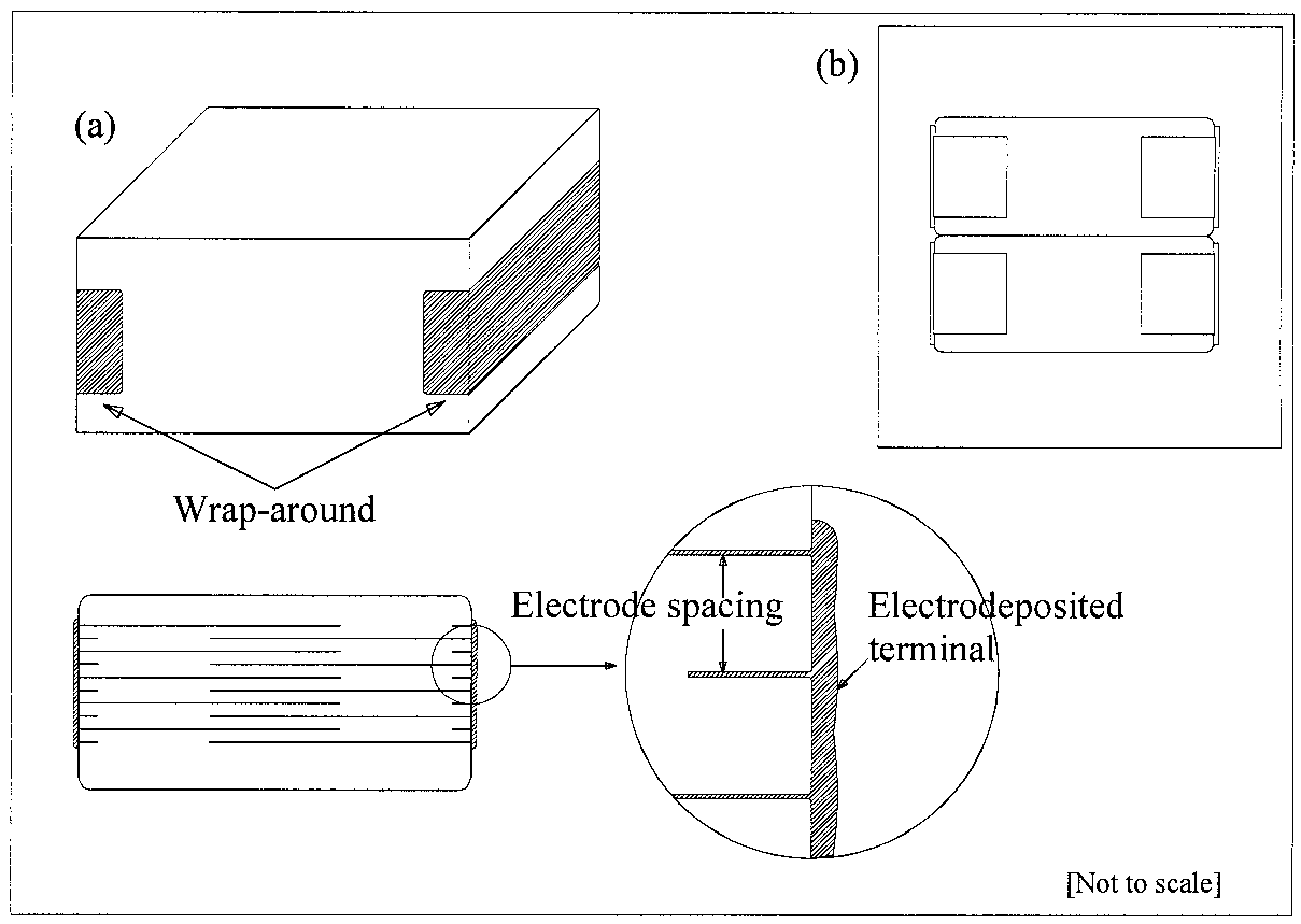
In this study, electrodeposition was examined as an alternative method to using cermet pastes in producing end terminals. To form the terminals it is necessary to selectively deposit a metallic layer on the electrode ends of the capacitor without depositing metal on the entire capacitor, as shown in Fig. 2. The traditional method to electroplate ceramic capacitors is barrel plating, in which parts are placed in a rotating nonconductive mesh basket immersed in a plating bath.3 Electrical contact to the parts is achieved with conductive plating media, normally metallic spheres. To use barrel plating, the exposed electrodes of the capacitor, which are areas on the order of 1 mm long and 1㎜ wide, first needed to be enlarged by electroless plating before electroplating. Therefore, the strategy was to use electroless copper followed by electroplated nickel onto the exposed electrodes.

Fig2
The three main challenges for producing electrodeposited terminals were selective deposition, adhesion strength, and electrical reliability. Selective deposition of the EDTC was achieved by using a combination of electroless copper and electrolytic nickel. To address the issues of adhesion and reliability, mechanical and electrical measurements of the EDTCs and standard silver terminal parts were made.
The EDTC consisted of three layers of plating: electroless copper seed layer, electrolytic nickel, and electrolytic tin–lead. Figure 3(a) is a micrograph showing the electroless Cu seed layer. The copper tended to be thin, spotty, and concentrated at the electrodes. The thickness of the copper deposit was estimated at 0.1–0.2 μm. The distance between electrodes was ~10μm.
The DFs for the EDTCs were also nearly identical to those of the standard parts. This shows that the plated deposits made excellent electrical connections to the electrodes. The EDTCs and the standard capacitor originated from the same batch of MLCCs. Thus, the only factor affecting DF that is not in common is electrode-to-terminal connections. Poor connections would have increased the equivalent series resistance (ESR) and would have resulted in higher DF measurements.
上一篇: 单晶硅的完整 3D蚀刻轮廓分析
下一篇: 多晶硅表面改性技术以减少微观结构的粘附