Iron-doped InP substrates with (i00) orientation and mirror-polished finish were used for the etch experiments. After degreasing in acetone and boiling methanol (5 min each) the wafers were dipped (20 s) in HF (5%), treated in H202 (5%) for 5 rain followed by a second 20 s HF (5%) dip. After a final rinse in DI water of 18 M~ the substrates were dried for 30 rain at 120~ and subsequently mounted into a turbopumped vacuum chamber. Layers of titanium (40 nm) were deposited on the front and back side of the wafers using E-gun evaporation. The background pressure during evaporation was maintained below 2 • 10 -6 mbar. The Ti layer was photolithographically patterned using Shipley S 1400-31 positive photoresist to form the mask for the Vgroove etching. Stripes of 178 to 206 ~m in width running parallel to the [011] and [011] directions were opened by removing the titanium under continuous motion in HF (40%):HNQ (65%):H20 (5:24:64) solution. After several rinses in DI water the samples were cut perpendicular to the stripes into pieces of 2 • 6 mm ~. Etching in 60 ml HCI (37%):H3PO4 (85%) (5:1) solution was preceded by a 1 min dip in concentrated HNO3 for a better uniformity and reproducibility. 9 The process was stopped after i to 20 rain by a thorough DI water rinse. Temperatures of i0, 20, and 40~ were selected for the etching which was performed without stirring. The etched profiles were inspected by scanning electron microscopy (SEM) and optical microscopy. Etch rates were extracted from the cross sections of etched grooves obtained after etching for eight different times. In order to evaluate the influence of the masking material additional experiments were performed. We used a 2 ~m thick epitaxial layer of the ternary alloy In0.~3Ga0.47As (InGaAs for short) which is lattice-matched to InP. Compared to InP the ternary layer has a negligibly low etch rate in HCl-based etchants. The InGaAs layer was photolithographically structured using a solution of H3PO4 (85%):H202 (30%):H20 (I:i:I0) which has a very low etch rate in InP.
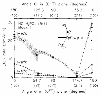
The prediction of the morphology of etched grooves requires detailed knowledge of the etch rate as a function of crystallographic direction. We limit the modeling to reaction-controlled etch processes so that care was not to be taken with respect to geometrical restrictions. The etched profiles can directly be constructed from the radius vectors r (O~) where r gives the etch rate into the direction characterized by the angle O~ as schematically shown in Fig. la. Normals are drawn to the tip of these vectors and the predicted cross-sectional profile is defined by an envelope of planes, which consists of all normals or portions of normals that may be reached from the origin atr = 0 without intersecting any others.
Figures 3 and 4 show the gradual development of the cross-sectional etch profiles of two orthogonal stripes of 200 bm width. The low-index surfaces, which according to the r (O) dependence depicted in Fig. 2 appear as possible sidewalls are drawn at the bottom of the figures. Initially, the slopes of the etched facets of [011] ((011))-oriented grooves are determined by those planes for which local minima in etch rate beginning at O = 0 ~ (180 ~ appear first with increasing (decreasing) O in the r (O) diagram (cf. Fig. 2). The minimum detected at 90 ~ exhibits a slightly lower etch rate compared to r (O = 54.7~ Therefore the {011} facets are clearly observable only after several minutes of etching whereas the {i i lIB planes develop immediately. For the (011)-oriented stripes the {211}A planes appear without delay. After i0 min of etching a V-shaped groove profile has formed as visible in Fig. 3. A tendency to develop facets of increasing slope due to a reduced etch rate with respect to the {211}A planes was observed after this period when the (i00) plane had completely vanished.
To establish a correlation between the shape of the wall profiles and the fabrication conditions the etch-rate ratios r~llljB/r~11o~ and r~l~B/r(~oo ) must be considered. Whereas r~10~ and therefore r~js/ri~lol is strongly influenced by the adhesive strength of the mask, r~B/r(loo) depends on the H3PQ content of the etch solution. ~ Single-slope facets ([111}B or {2 ll}B planes) were observed if both ratios are small corresponding to large mask undercutting and the use of pure HC1 or HCI:H3PQ (5:1) etchants. 3'~ Vice versa facets vertically oriented to the (100) plane were obtained if both ratios are large corresponding to small mask undercutting and an H3PO4 content in the etch solution of more than "75%.3 '~~ In the mixed case of large r~/r~no~ and small r~)~/r(~oo) double-slope wall profiles of irregular shape are expected as observed in Ref. 3 and the present study and single-slope facets leading to perfect V-grooves oriented in [011] direction will not develop.

Fig1
The undercutting of the Ti mask predicted and measured for both stripe orientations and the whole temperat.ure range is displayed in Fig. 7. As expected the undercut rate for the [011]-oriented stripes was found to be considerably higher than that of perpendicular stripes. The time scales of the three sections in Fig. 7 are adjusted to-the etch time required for complete V-grooves to develop. We explain the unexpectedly high undercutting at T = 10~ by a loss os adhesion of the mask to the InP substrate during the prolonged etch process (cf. Fig. 7a). Thus, the optimum temperature with respect to small undercutting lies around 20℃.
上一篇: 局部湿蚀刻法制备硅玻璃凹微透镜阵列