Thermal reflflow is a commonly used technique to fabricate microlens features in the photoresist (PR).1 These PR microlenses can be transferred onto other materials by etching to form convex lenses or by molding to form concave lenses on different substrates, such as GaN, sapphire, and diamond. These microlenses have a broad range of applications in optoelectronics and laser optics. Our work here is particularly motivated by the pattern transfer into diamond, which has excellent properties for photonic applications, such as transmittance over a broad spectral range and high Raman gain.
Up until now, microlenses are typically fabricated by thermal reflflow of a single PR layer and subsequent pattern transfer by inductively coupled plasma (ICP) etching. This approach is attractive due to its simplicity, high reproducibility, and the high surface quality of the resulting microlenses. The engineering aspects of this particular method have been studied and extensively reported in the recent past. However, even though the PR reflflow step plays a crucial role, only little is known about the detailed mechanisms that determine the exact shape of the reflflowed PR. A controllable way of fabricating PR lenses with different dimensions and ROCs has not been reported yet.
bulge at the edge of lithographically defifined PR patterns upon thermal reflflow. We refer to this as the “edge bulge effect.” To our knowledge, this effect has not been investigated in depth before. There are a couple of known bulge formations that at fifirst may appear similar, namely, the “coffee stain effect” in liquid droplets upon solvent evaporation,20,21 the “edge bead effect” in spin coating, and the bulges associated with moving contact lines during PR deposition. However, the edge bulge effect reported here is distinctly different from these known effects. We examine the evolution of the edge bulge as a function of the reflflow temperature and the initial thickness of the PR patterns and derive an empirical formula describing the relationship. Based on this examination, a controllable fabrication of PR patterns is realized via the reflflow method.
Additionally, a previously unreported minimum thickness at a certain reflflow temperature for the formation of a convex reflflowed microlens shape on PR patterns is observed and characterized. It was further shown that the PR microlens formed at this minimum initial thickness has the largest ROC at its diameter. Based on the study, a PR microlens pattern with the largest reported ROC of 1.4 mm at a diameter of 400 lm is achieved.
Furthermore, a controllable diamond microlens fabrication process is developed based on the investigation of PR reflflow and the ICP etching with a low etching selectivity. The process developed enables the realization of high quality diamond microlenses with a ROC > 10 mm, which has not been achieved before. As a result, single crystal diamond microlenses with a diameter of 400 lm and a stateof-the-art ROC of over 13 mm have been realized.
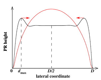
A schematic illustration of the edge bulge effect is shown in Fig. 1. The curve with arrows represents a profifile with edge bulges. As the reflflow temperature and/or PR thickness is increased, the bulge propagates inwards as indicated by the arrows until eventually a convex lens of approximately the spherical shape (spherical curve) is formed. The edge bulge propagation is fifirst investigated on large 1 X 1 mm2 square PR patterns, which minimizes the interaction between the bulges.

Fig1
In Fig. 5, the minimum PR thickness required for lens shape formation with a given lens radius at a reflflow temperature of 125 C on silicon is plotted. Similar behavior has also been observed for PR patterns on diamond. Therefore, the above fifinding can be used as a guideline for the fabrication of PR microlenses on diamond as well.
Furthermore, it was found that the PR lens shape formed at the minimum initial thickness had the largest ROC at its diameter. Based on this result, a PR microlens pattern with the largest reported ROC of 1.4 mm at a diameter of 400 lm is achieved. As shown in Sec. III, such PR microlens pattern with the largest ROC has been successfully transferred onto diamond to form large ROC diamond microlenses.
Very few theoretical investigations have been made that consider more complex shapes. Audran et al. numerically solved the Navier-Stokes equations and were thus able to model the temporal evolution of the droplet, including intermediate shapes that contain an edge bulge. However, their fifinal shape still does not have an edge bulge. Since the edge bulge observed by us does not represent an intermediate temporal shape, it is questionable if it can really be explained by this model. O’Neill and Sheridan summarized a number of fifitting procedures for the recorded pattern profifiles that account for complex surface shapes. While these fifitting methods may be useful for engineering purposes, they do not give any insight into the physics causing the observed shapes.
下一篇: 半导体晶片的氢氟酸和盐酸蒸汽处理