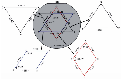
The etching characteristics of concave and convex corners formed in a microstructure by the intersection of {111} planes in wet anisotropic etchant are exactly opposite to each other. The convex corners are severely attacked by anisotropic etchant, while the concave corners remain unaffected. In this paper, we present a new model which explains the root cause of the initiation and advancement of undercutting phenomenon at convex corners and its absence at concave corners on {110} silicon wafers. This contrary etching characteristics of convex and concave corners is explained by utilizing the role of dangling bond in etching process and the etching behavior of the tangent plane at the convex corner. The silicon atoms at the convex edge/ridge belong to a high etch rate tangent plane as compared to {111} sidewalls, which leads to the initiation of undercutting at the convex corner. On the other hand, all the bonds of silicon atoms pertaining to concave edges/ridge are engaged with neighboring atoms and consequently contain no dangling bond, thus resulting in no-undercutting at concave edges/corners.
Silicon micromachining is extensively performed using wet anisotropic etching for the fabrication of simple cavities to complex structures [1-5]. Moreover wet anisotropic etching is inevitable if the microstructures with slanted sidewalls are to be fabricated. This method of etching exploits variations in the etch rates of the low index crystallographic planes (i.e. {100}, {110}, {111}, etc.). The major advantages of wet etching include lowcost and batch process besides others, which are indispensable requirements for the minimization of fabrication cost leading to the cost reduction of the end-product. Due to these factors, silicon wet anisotropic etching is an important area of research in the field of microelectromechanical systems (MEMS).
In wet anisotropic-based bulk micromachining, the selection of wafer depends upon the type of structure to be fabricated. For instance, rectangular/square shaped cavities/grooves are fabricated in {100}Si wafers while {110}Si is used for fabricating microstructures with vertical as well as slanted sidewalls. In the {100}-oriented silicon wafer, four {111} planes, which are oriented at an angle of 54.7˚ to the wafer surface, are exposed during anisotropic etching of a circular (or arbitrary shaped) mask opening as shown in Figure 1. In the case of {110}-oriented wafer, six {111} planes are exposed as illustrated in Figure 2. These planes intersect the {110} surface in the form of a hexagon. Two of the six {111} planes emerge at <110> direction, and are oriented at an angle of 35.3˚ to the {110} wafer surface, while the other four {111} planes appear at <112> directions and are vertical to the {110} surface. The appearance of vertical planes along <112> direction makes {110} silicon wafer an appropriate choice for the formation of deep trenches/ grooves with vertical sidewalls [4-10]. In both these types of wafers, prolonged etched patterns are generally bounded by {111} planes due to their slowest etch rate nature in all kinds of anisotropic etchants.
This paper presents a new model to explain the etching characteristics of concave and convex corners on {110}Si wafer. It describes the initiation of undercutting at convex corners, which are formed by the intersection of {111} planes in {110}Si wafer, during wet anisotropic etching process. Moreover it explains the inhibition of undercutting (or no-undercutting) at concave corners which are also formed by the intersection of {111} planes.

Fig1
As described in the previous section, the etching characteristics of concave and convex corners are opposite to each other. The convex corner are badly damaged in anisotropic etchants, whereas no damage occur at concave corners. As shown in Figures 2-4, {111} planes intersects each other forming either an acute angled or an obtuse angled corner. As illustrated in Figure 4, at the acute angled convex corner, the silicon atoms at the convex edge contain two dangling bonds while the {111} planes forming the edge consist of atoms with only one dangling bond. In the case of obtuse corners, the atoms of convex ridge as well as the {111} sidewalls planes comprise one dangling bond. The number of dangling bonds at the acute angled convex corner is more than the neighboring {111} planes which makes it more reactive in anisotropic etchants. As a result the acute angled convex corner experiences heavy undercutting and is badly damaged as the etching proceeds. However in the case of obtuse angled convex corner, the convex edge as well as the neighboring {111} planes consist of atoms carrying only one dangling bond, but it also encounters heavy undercut. Hence, the concept of dangling bond alone cannot be exploited to explain the undercutting at all types of corners. In this work, a very simple model is developed to explain the undercutting at all kinds of convex corners as well as the no-undercutting at concave corners.
The etched profile of the sidewalls appearing at the masked edges can easily be determined using WulffJaccodine method (Figure 8) [5,23,24]. In this method, the etched profile is estimated by the distribution of the etch rate vectors existing in the planes belonging to the mask edge from where the etched sidewall profile will appear. The mask edge (or line) is called the zone axis of the planes passing through it. The etch rates of the planes of any zone axis can be determined by the etch rate data of emisphere [21,24]. The sidewall profile of the etched pattern at the masking edge is the minimal envelop of all intersecting lines which are perpendicular to the etch rate appearing at the mask edge are the minimum etch rate planes between the horizontal plane and vertical plane at that edge. Similarly the etched profile of undercut structure are estimated. In this case, the sidewalls are the minimum etch rate planes at the maximum lateral underetch rate direction.