This paper presents the electrical and thermal analysis of an OLED module. The OLED module consists of the OLED element and the DC-DC converter incorporated in its backplane. The DC-DC converter is realized as an integrated circuit and uses an external inductor. The inductor is embedded in the substrate of the backplane and has a spiral geometry. The DC-DC converter is highly efficient, but a fraction of the electrical power is dissipated in the integrated circuit and the planar inductor. This thermal dissipation has a negative consequence on the OLED characteristics. Additionally the planar inductor represents a loop antenna that radiates electromagnetic energy. The radiated disturbance of the planar inductor must conform to the EMC standards. The COMSOL Multiphysics is used to investigate both the electromagnetic and thermal performance of the OLED module.
The electronics on flexible foils is an area of intensive research and development. The electronics on flexible foils include the areas of wearable electronics, lightning devices and displays. Such electronics applications may require a power source embedded in the flexible foil and DC-DC converters are regularly used for this purpose because of their high efficiency.
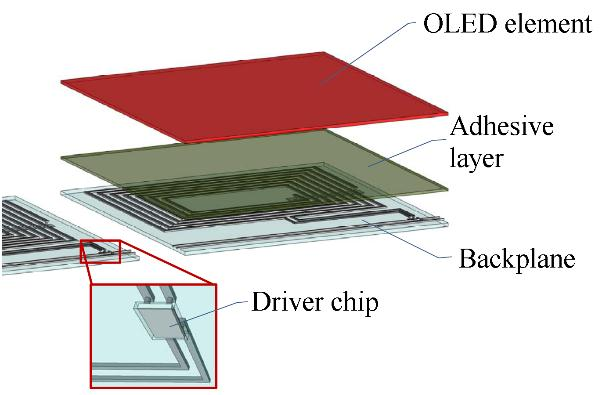
The OLED module analysed in this paper is powered by a DC-DC converter consisting of an integrated circuit and a planar spiral inductor. The integrated circuit and the planar inductor are embedded in the PET foil and form the backplane of the OLED module. The backplane is connected to the OLED tile via an adhesive layer. Figure 1 shows the general structure of an OLED module.
The DC-DC converter of the OLED module places a number of requirements on the electrical characteristics of the inductor. The series inductance needs to be in a certain range for the converter to operate properly. The series resistance and the port capacitances need to be low enough to reduce the power dissipation. The resonant frequency needs to be significantly higher than the operating frequency of the converter f = 10 MHz.
The OLED is made of the organic material that is extremely sensitive to thermal influences. The critical parameters that need to be fulfilled for normal operation of the OLED element is the operating temperature and the maximum temperature difference across the OLED element. Exceeding these requirements contributes to accelerated aging of the OLED element and its uneven illumination.

Fig1
The RF Module is used in simulations to evaluate the electrical characteristics of the planar inductor and then to evaluate the far-field radiation and the heat dissipation due to the resistive losses. The planar inductor is a 2 port structure and it is defined by two Lumped Ports. The electrical characteristics are evaluated based on S-parameters. The RF Module is in this case used to make the port sweep and the Lumped Ports are set to Cable terminal type. When evaluating the far-field radiation and the inductor heating, the Lumped Ports are set to the Current Terminal port.
The thermal modelling is based on the heating produced by the planar inductor and the DC-DC converter integrated circuit. The planar inductor is defined as a Boundary Heat Source and it is coupled with the RF Module physics via the emw.Qsrh variable. The integrated circuit is as well defined as a Boundary Heat Source over a 2x2 mm2 boundary area. Its total boundary power is set to the approximated thermal dissipation of the integrated circuit. The heat spreader is defined as a Highly Conductive Layer thus avoiding the meshing of very thin films similarly as in the RF Module. The heat spreader is defined in place of the OLED cathode.
The model executes two separate studies. The first study sweeps the ports over a range of frequencies and thus produces the S-parameters of the planar inductor. The second study consists of two steps; the first step solves the Electromagnetic Waves physics in the frequency domain for a single frequency and the second step solves the Heat transfer physics in the stationary state. The second study sweeps the heat spreader thickness in a logarithmic manner.
下一篇: 一种测量OLED材料介电强度的方法