We report the results of diffuser lithography applied to a negative-type thick photoresist to fabricate 3-dimensional microstructures suspended on supports. When UV light passes through a diffuser film, the direction of the light is randomized because of the irregular surface of the diffuser. By exposing through a diffuser on a Cr-mask, a circular or an elliptical cross-section of exposed region can be formed on a spin-coated photoresist. When applied to a negative-type thick photoresist, diffuser lithography gives a 3-dimensional circular cross-section of the exposed and cross-linked regions, which could be used for making suspended microstructures. The size of the exposed region has been controlled by the dose of the UV light. The current study clearly shows that the depth of exposed region of photoresist is affected by the geometry of the pattern. By controlling the depth of the exposed region using different pattern size, beam structures suspended on the support structures could be fabricated by single exposure process. The characteristics of the diffuser lithography process were investigated on a negative type photopolymer, SU-8, with different doses of UV-light and different geometry.
Recently, with enhancements of MEMS/NEMS technology, the need for the fabrication of 3- dimensional microstructures with special functions has increased. Photo-lithography is a common method for making microstructures, but it has a limitation in making three-dimensional microstructures such as bridge-type structures which are supported on both ends or cantilever-type structures supported on one end by support structures.
Yu reported a scanning laser technique to fabricate 3-D structures, e.g., cantilevers and bridges, on SU-8. Suzuki et al. reported an inclined UV exposure method to make an embedded microchannel with single mask process. Chang and Yoon proposed a diffuser lithography, which uses UV exposure through a diffuser film on a positive-type photoresist to make rounded cross-section of micro-lens array mold. Because the diffuser lithography proposed by Chang uses the conventional lithography process with addition of a diffuser film on Cr-mask, it showed some advantages of process simplicity, reproducibility and various shapes of cross-section. The cross-section shape varies by changing the sort of diffuser, exposure dose, mask pattern width, and proximity gap. However, in Chang’s report, because they were interested in optical device application which requires uniform pattern size, the investigation about the effect of mask pattern size and geometry was not reported.
In order to get the rounded cross-section on photoresist by using diffuser lithography, the process parameters are controlled so that the light is diffused in the resist and does not reach the bottom surface of the substrate. When diffuser lithography is applied on a positive type photoresist, only the part of the resist exposed by diffused light is removed and the other part remains on the substrate. This remaining photoresist can be used as a mold structure for replication of various micro patterns with rounded shapes. On the other hand, at negative type photoresist, exposed parts are cross-linked and other unexposed parts are removed by development. This means the exposed parts are not on the substrate and will be washed away from the substrate if they have no support structures on the substrate. Therefore, in the diffuser lithography on a negative type photoresist, investigations on the relations between the depth of exposure and process parameters are necessary in order to ensure the connection of microstructures on the substrate surface.

Fig1
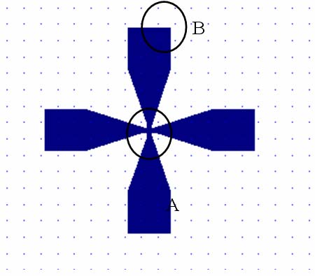
Fig. 6 shows a schematic diagram of the difference of exposure depth according to the pattern size in the diffuser lithography. When the open part of the metal layer on the Cr-mask is small, the light diffuses and the light cannot reach the bottom of the resist, which means that the cross-linked region would be suspended after developing. On the other hand, when the open pattern of the Cr-mask is big, the UV lights diffused from different point are superposed and finally get enough of a dose to make depth of exposure large enough to reach down to the substrate, which allows it to form a support structure in a negative-type resist.
As shown in Fig. 7, a wider slit pattern in the Crmask gave a bigger beam width and thickness because more UV-light could go through the wider slit of the Cr-mask. When comparing the width and thickness of the beam structure at the both ends and at middle point of the bridge, the beam had a bigger width and thickness at both ends than in middle point of the bridge structure. This is attributed to geometry effect. In the corner part, where slit and square meet, the number of photons is larger than in the middle of slit because it has more directions for diffused photons to come. In the middle point, apart some distance from the junction of slit and square, the beam width and thickness could be kept uniform. Fig. 8 shows the exposure width according to exposure time. As the exposure time increases, the width increases. Fig. 9 shows the exposure depth measured by beam thickness according to the exposure dose and slit width.
下一篇: 一种制造毫米波波导元件的新方法