Abstract: Gel fibers prepared based on microfluidic laminar flow technology have important research value in constructing biomimetic scaffolds and tissue engineering. The key point of microfluidic laminar flow technology is to find the appropriate fluid flow rate in the micropipe. In order to explore the influence of flow rate on the laminar flow phenomenon of a microfluidic chip, a microfluidic chip composed of an intermediate main pipe and three surrounding outer pipes are designed, and the chip is prepared by photolithography and the composite molding method. Then, a syringe pump is used to inject different fluids into the microtubing, and the data of fluid motion are obtained through fluid dynamics simulation and finite element analysis. Finally, a series of optimal adjustments are made for different fluid composition and flow rate combinations to achieve the fluid’s stable laminar flow state. It was determined that when the concentration of sodium alginate in the outer phase was 1 wt% and the concentration of CaCl2 in the inner phase was 0.1 wt%, the gel fiber prepared was in good shape, the flow rate was the most stable, and laminar flow was the most obvious when the flow rate of both was 1 mL/h. This study represents a preliminary achievement in exploring the laminar flow rate and fabricating gel fibers, thus offering significant reference value for investigating microfluidic laminar flow technology.
1. Introduction
Micro-nano-sized gel fibers with a large specific surface area hold great promise for applications in the biomedical field, enabling the simulation of in vivo microenvironments . Currently, various methods are employed to prepare gel fibers, including electro-spinning technology, wet-spinning technology, and microfluidic technology. Nagrath et al. successfully developed bioactive gel fibers by combining the sol-gel method with electro-spinning technology. These fibers serve as carriers for bone regeneration, cell proliferation, wound healing, and drug delivery. Due to their biomimetic properties, they have broad potential in soft tissue repair and angiogenesis. Similarly, Zheng et al. utilized electro-spinning technology to create an artificial neural catheter using PLLA and porcine decellularized neural matrices as materials. Through histological evaluation and immunostaining analysis in rat implants, they demonstrated that the artificial neural catheter promoted nerve axon extension and nerve fiber formation. Furthermore, Xu et al. employed wet electro-spinning technology to produce nano-reinforced ceramic composite fibers in situ. These fibers retained the amorphous structure of the material, increased porosity, and improved fracture toughness, resulting in significant hardening and toughening effects on polymer composites. However, both electro-spinning and wet spinning methods can potentially damage cells when perfused during fiber preparation.
2. Materials and Methods
2.1. Materials
The PDMS (Sylgard 184) was obtained from Dow Corning, headquartered in MidlandMI, USA. Ultra-pure water, polyvinyl alcohol (PVA), rhodamine B, sodium alginate, CaCl,and anhydrous ethanol were procured from Aladdin Biochemical Technology, situatedin Shanghai, China. The photoresist (AZ-50XT) and developer were sourced from AZElectronic Materials, situated in Somerville, NJ,USA.
2.2. Methods
2.2.1. Preparation of Microfluidic Chips
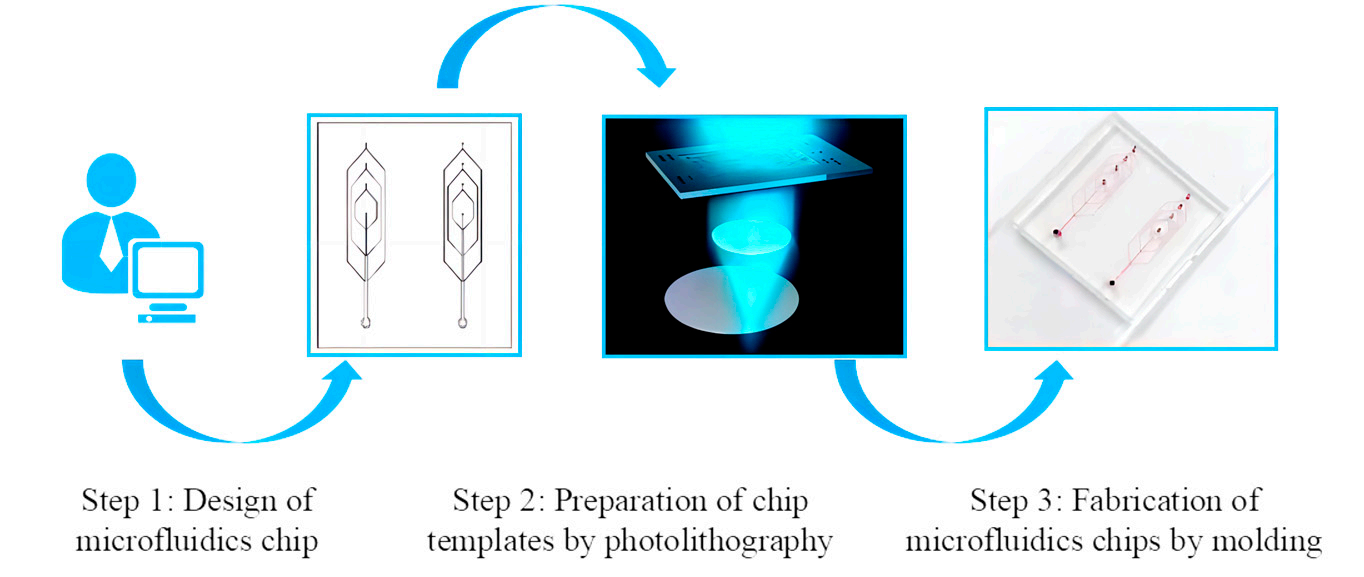
Step 1: The microfluidic chip was designed using Solidworks version 2021 software(Dassault Systemes SolidWorks Corporation, Coventry, UK), as depicted in Figure 1. Thechip consists primarily of two types of channel. The central vertical channel serves thepurpose ofintroducing the inner phase fluid, which contributes to the formation of a hollowfiber structure. The main pipe size gradually increases from top to bottom, starting from50 um and progressing to 100, 150, and finally 200 um, following a narrowing-to-wideningpattern. The outer region of the chip features a three-ring annular channel, specificalldesigned for introducing the external phase fluid responsible for forming the fibers. Thediameter of the circular channel is set to 50 um.

Figure 1. The preparation process of a microfluidic chip
2.2.2. Fluid Injection Mode
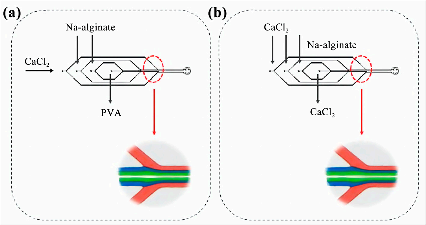
In order to achieve laminar flow, it is necessary to introduce each fluid into the system through distinct microtube inlets, while maintaining a constant flow rate. Once injected, the fluid gradually travels through the micro duct until it reaches the intersection point. There are two distinct methods of injection, as depicted in Figure 2:

Figure 2. Fluid injection: (a) the first injection method; (b) the second injection method
In the first approach (Figure 2a), the intermediate pipeline contains a 10 wt% PVAsolution, while the inner two layers consist of a 1 wt% sodium alginate solution. Theoutermost layer is composed of a 01 wt% CaCl, solution.
3. Results and Discussion
3.1. Microfluidic Chip
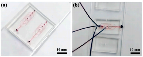
Using a 1 mL syringe, the stained fluid is injected through a syringe pump into themicrotubing of the microfluidic chip to explore the state of fluid flow (Figure 3).

Figure 3. Microfluidic chip fluid experiment diagram: (a) Microfluidic chip; (b) Stained flu
4. Summary
This paper presents the design of a microfluidic chip that eliminates the need for hydrophilic modification of microchannels and offers a convenient operation process. A series of comparative experiments were conducted to investigate the effects of different fluid compositions and flow rates. The results indicate that the utilization of sodium alginate as the outer solution, CaCl2 as the inner solution, and a flow rate of 1 mL/h for both layers enables the preparation of hollow structural fibers with superior morphology. Furthermore, this configuration ensures the most stable fluid movement and the occurrence of distinct laminar flow phenomena. The findings of this study serve as a valuable reference for exploring the influence of flow rate on the laminar flow phenomenon in microfluidic chips.
上一篇: 评估微流体流动条件下的微分颗粒变形能力
下一篇: 晶硅片各向异性表面制绒工艺实验分析