Abstract.
The rich variety of micron-scale features observed in the orientationdependent surface morphology of crystalline silicon during anisotropic wet chemical etching is shown to have its origin at the atomistic scale. Realistic Monte Carlo simulations show that the pyramidal hillocks on Si(100) are the result of local stabilization of distributed apex atoms by (metal) impurities from solution. In the absence of this stabilization, shallow round pits are formed on Si(100) as a result ofthe anisotropy between (onelayer deep) pit nucleation and (isotropic) step propagation. It is also concluded that nosed zigzag structures at vicinal (110) are the combined result of misaligment and the etching anisotropy, showing that the nucleating mechanisms of morphologically related structures such as pyramidal hillocks and nosed zigzags are not necessarily the same. The simulations confirm that the formation of (one layer deep) triangular and hexagonal pits on exact Si(111) and of polygonal (saw-shaped) and straight terraces in vicinal Si(111) depends on the relative rate of [1¯ 21] and [¯ 12¯ 1] step propagation and on the misorientation of the surface with respect to Si(111).
1. Introduction
Anisotropic wet chemical etching remains the most widely used processing technique in silicon technology. Used in combination with a multitude of other processes, it has a wide range of applications in microelectromechanical systems (MEMS), including pressure, acceleration, angular rate and gas-flow sensors, actuators, nanoprobes , nanowires, micromirrors, laser cavities, optical switches, aligment grooves and microvalves, to mention only a few. Its wide presence is not only due to its ease of use and low cost, but also due to the fact that it provides fairly smooth surfaces with no physical damage to the bulk. However, in the past few years, the roughness of the etched surface has begun to play an increasingly important role as the size of the devices is continuously reduced. The performance of a growing number of micromechanical devices requires very smooth surfaces and the precise production conditions need to be found. It has become apparent that there is a need to improve the understanding of the process in general and, in particular, of the mechanisms that lead to the characteristic morphological features of the etched surfaces.
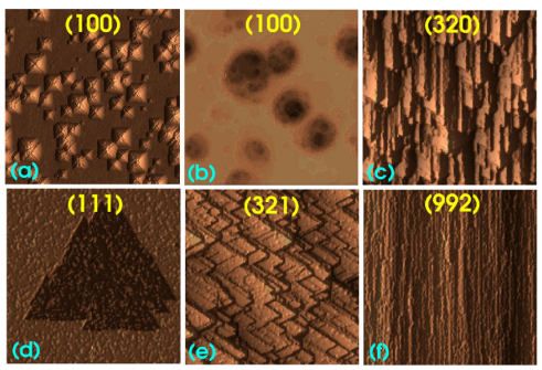
Systematic studies of the dependence of the surface morphology on orientation have provided a more general perspective on the problem, establishing morphological relations between some of the surface features such as the pyramidal hillocks on Si(100) and the nosed zigzags on Si(110) or the formation of polygonal-stepped (figure 1(e)) and straight terraces (figure 1(f)) in vicinal Si(111). Also, from a more general perspective, the specific features of the surface morphology in anisotropic wet chemical etching of silicon are only an example of a wider range of morphological features observed in other etched or grown materials. An improved understanding of the mechanisms generating these features in wet chemical etching may help in other disciplines.

Figure 1. Most frequent (simulated) morphological features during wet chemical etching. (a) Pyramidal hillocks on (100). (b) Round shallow pits on (100). (c) Nosed zigzags on vicinal (110). (d) Triangular pits on (111). (e) Polygonal steps on terraced vicinal (111). (f) Straight steps on terraced vicinal (111) (cf figures 2(g), 8 (top), 12(f), 14(i) and 13(f) and (a), respectively).
2. Simulation results for pyramidal hillocks
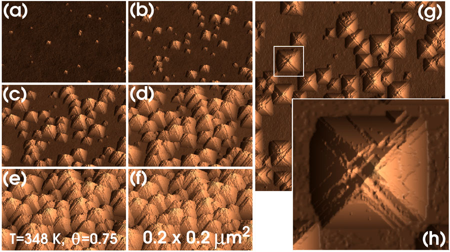
In this section we show the results of simulations using the parameters of case A (table 1) at different temperatures and coverages. Figure 2 shows the typical time evolution of the (100)- surface morphology. Initially, the morphology is characterized by nucleation and growth of pyramidal hillocks. At any time, pyramids of different sizes are observed, reflecting the fact that hillocks are nucleated continuously during the etching process. For long etching times, complete surface texturization by the hillocks is obtained, in agreement with experiment. Note that, as in the experiments, the simulated hillocks are not geometrical objects with flat facets joining at a single apex. Instead, they contain rather irregular edges along the<110> -directions (figure 2(g)) and closer inspection shows that several points simultaneously share the function of the apex (figure 2(h)). Also, the flat (111) facets have a complex terraced structure, as shown in figure 2(h). This feature corresponds well with the fact that, after pit nucleation, the {111} surfaces are etched by a step propagation mechanism resulting in the formation of terraces, as will be shown in section.

Figure 2. Surface texturization of Si(100). From (a) to (f), the snapshots are taken at 5, 10, 15, 20, 25 and 30 × 103 Monte Carlo time steps. (g) Top view of (c). (h) Highlighted region in (g).
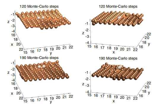
A series of snapshots is used in figure 3 to show the typical nucleation mechanism for the formation of a pyramidal hillock. The hillocks are nucleated as a result of the stabilization of the initial apex atom due to the attachment of two metal impurity atom/ions from the solution. Note that, although not shown, the attachment of the two impurities is sequential (i.e. it does not usually occur simultaneously). In the simulations, we assume that the impurities interact with the singly coordinated silicon atoms, replacing them instantaneously. Effectively, the metal impurities are represented by the singly bonded silicons. The number of metal impurities on the surface is controlled by adjusting the parameters E1 and p1 entering the removal probability of singly coordinated silicons. This approach for the incorporation of metal impurities on the surface will prove satisfactory for the description of the temperature and coverage dependence of the surface density of hillocks (section 3.4). Note that the microscopic process effectively controlling the nucleation of a pyramid is the disclosure of singly coordinated atoms. In principle, these disclosures can occur in various multiple ways through the removal of two or three-bonded atoms and, effectively, they cannot be associated with a single atomistic process.

Figure 3. Mechanism for nucleation of hillocks. Time increases from top to bottom. The left and right columns show the same scene from two different points of view. Surface atoms are represented as coloured balls lying on a smooth surface. The two impurities nucleating the hillock are shown as meshed balls.
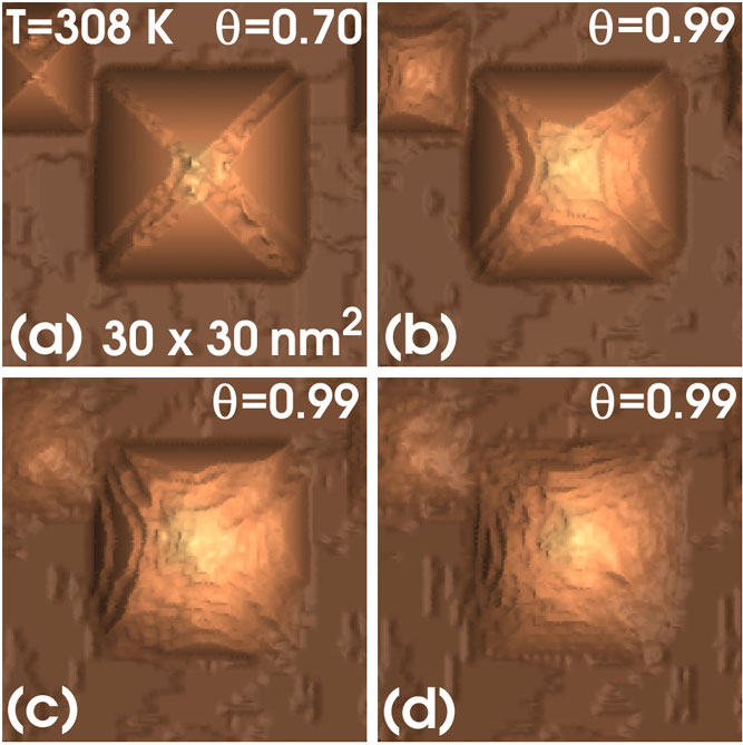
The removal of the stabilizing impurities will result in the destabilization of the apex atom and, thus, of the hillock. However, the hillock may be restabilized again by the new attachment of impurities to one or more surface atoms at the top region. This explains the appearance of distributed apex structures, in agreement with experiments. In this way, if there are enough impurities and their removal is not very frequent, the pyramids can grow from their bottom down as the wafer surface evolves downwards at a faster rate than the pyramid tops. Note that, in addition to stabilized tops and fast removal of bottom-surface atoms, the formation of a pyramid requires two extra conditions: the stability of {111}-facet atoms (TM or type 3A) and the stability of ridge atoms (SM or type 3B). This is automatically provided in our model by the backbond weakening effect of the terminating OH groups. The atoms of type 3A are backbonded to three bulk atoms through strong bonds since, at most, the bonds are weakened by one OH group. In turn, the atoms of type 3B are bonded to one bulk atom and two surface atoms so that, typically, two of the bonds are weakened by two OH groups each and the third bond is weakened by only one group. Thus, under all possible conditions, this makes the removal of ridge atoms more probable than that of facet atoms. This explains the appearance of terraced structures at the interfacet region of the pyramids and the formation of macrosteps (in the sense of more than one layer thick) as observed in figure 2(h). This also explains why, in the absence of stabilizing impurities, the pyramidal hillocks are removed by direct attack to the ridge regions, as figure 4 shows. In this figure, a pyramidal hillock grown in similar conditions as those for figure 2 is re-etched at higher coverage and lower (non-zero) impurity concentration, keeping the temperature constant.

Figure 4. Elimination of pyramidal hillocks. After 2.0 × 10⁴ MC steps (a), a reetch process is initiated. Snapshots are shown after 5 × 10³ (b), 10 × 103 (c) and 15 × 103 (d) MC steps.
3. Morphology of other orientations
In this section we consider the morphology of other surface orientations for cases A and B. It is shown that the surface features of any orientation can always be related to either exact Si(110), misaligned Si(110), exact Si(111) or misaligned Si(111), in agreement with experiment. In addition to demonstrating that the most relevant morphologic features in wet etching have an atomistic origin, the most important result of this section is that the mechanism producing zigzag structures on vicinal (110) is not the same as the mechanism producing pyramidal hillocks on (100).
4. Conclusions
It is shown that the most relevant surface features observed during anisotropic wet chemical etching of crystalline silicon, such as pyramidal hillocks and shallow round pits on (100), nosed zigzags on vicinal (110), polygonal and straight terraces on vicinal (111) and triangular pits on exact (111), have their origin at the atomistic scale.
It is concluded that the pyramidal hillocks on (100) are the result of local stabilization of distributed apex atoms by (metal) impurities from solution. Further work is needed in order to address the technical question of whether the impurity atoms replace the singly coordinated silicons (as assumed in this study) or the impurities simply terminate them or interact in some more complicated manner. Also, the possibility that the impurities may catalyse the re-deposition of silicon should be considered.