Abstract: A thermo-mechanical wafer-to-wafer bonding process is studied through experiments on the glass frit material and thermo-mechanical numerical simulations to evaluate the effect of the residual stresses on the wafer warpage. To experimentally characterize the material, confocal laser profilometry and scanning electron microscopy for surface observation, energy dispersive X-ray spectroscopy for microstructural investigation, and nanoindentation and die shear tests for the evaluation of mechanical properties are used. An average effective Young’s modulus of 86.5 ± 9.5 GPa, a Poisson’s ratio of 0.19 ± 0.02, and a hardness of 5.26 ± 0.8 GPa were measured through nanoindentation for the glass frit material. The lowest nominal shear strength ranged 1.13 ÷ 1.58 MPa in the strain rate interval to 0.33 ÷ 4.99 × 10⁻³ s −1 . To validate the thermo-mechanical model, numerical results are compared with experimental measurements of the out-of-plane displacements at the wafer surface (i.e., warpage), showing acceptable agreement.
1. Introduction
Among the different bonding technologies, glass frit (gf) wafer-to-wafer bonding is well established and widely used, since it allows safely and economically enclosing microelectromechanical systems (MEMS) for numerous applications. It also prevents the contamination of MEMS in the cavity during the subsequent fabrication processes, such as dicing . This technology includes screen printing of a glass paste, its thermal conditioning, and then a thermo-compressive bonding process. It is important to remember that the packaging cost of an individual device can reach a significant portion of the total cost and therefore efficient wafer-level packaging can save a significant amount of money. The gf bonding procedure provides hermetic sealing, a reasonable stress level at the bonding interface, high strength and reliability, together with the possibility to incorporate metallic feed throughs.
A disadvantage, however, resides in the wafer warpage due to the coefficient of thermal expansion mismatch between silicon and gf and due to other sources of residual stresses arising during the bonding process. For this reason, several studies have investigated and modeled this process, with emphasis on its residual stresses and the characterization of the obtained material.
2. Glass Frit Experimental Characterization
In gf bonding, silicon wafers are sealed through a thermo-mechanical process by exploiting low melting point glasses, i.e., lead or lead-silicate glasses, as an intermediate layer. The glass transformation into the viscous paste is critical in this method; hence, there are criteria to obtain a high bonding quality, e.g., controlling the grain size. The knowledge of gf properties and its thermo-mechanical behaviour are of paramount importance for the modelling, simulation, and critical understanding of the bonding process which leads to residual stresses and wafer warpage. The gf material used in this research is a lead–silicate glass (DL11-036) made by Ferro. Oxides contained in the glass are reported in Table 1.
Table 1. Oxide content as a percentage for the gf material.

Since by combining with the process, the material composition influences the mechanical behavior, Section 2.3 reports the gf microstructural study through scanning electron microscopy (SEM) and energy dispersive X-ray spectroscopy (EDX). The filler also has the role of reducing the coefficient of thermal expansion (CTE), which in this case was equal to 9 × 10⁻⁶ °C−1 , as reported in the material data sheet.
2.1. Confocal Laser Profilometry
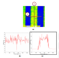
Surface roughness plays a secondary role in gf wafer level packaging because during the thermo-compressive bonding the glass reaches a wetting temperature causing the material to become soft enough to flow and fuse with the wafer surface layer at the atomic level; after cooling, the obtained bond can be quite strong. The material retains a low viscosity in order to avoid flooding the cavity where the MEMS is placed. Therefore, it is the temperature more than the pressure that is important, the former in the range 425–450 °C, the latter necessary to deal with a possible wafer bow and warp. However, in the initial temperature rise, the wafers are put into contact with the gf in between by applying a mechanical pressure in addition to the partial glass melting; hence, the gaps induced by the roughness between the gf film and the silicon wafer are compensated if they are not excessive. To study the topology of gf film as well as its surface roughness, confocal laser profilometry tests were carried out on pre-bond specimens. In this test, two different probe paths, longitudinal and transversal, as depicted in Figure 1a, were selected. The longitudinal profile travelled on the gf layer surface and determined the mean height of the asperities, while the transversal profile measured the height with respect to the silicon surface, considered as the reference plane. The corresponding height profiles for each path are presented in Figure 1b,c. The surface roughness parameters, in addition to the topological parameter of the gf film obtained from the profiles, are reported in Table 2.

Figure 1. Confocal laser profilometry scanning paths and corresponding height profiles: (a) probe paths in the laser profilometry test (Path 1: longitudinal, Path 2: transversal); (b) profile from longitudinal Path 1; (c) profile from transversal Path 2.
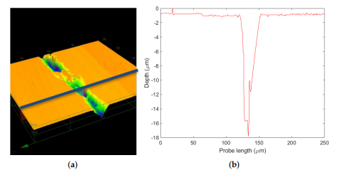
Another set of tests was carried out for post-bond specimens along the thickness on a silicon die (with the Si–gf–Si structure mentioned above). By performing the profilometry on the cross section of this structure (blue line in Figure 2a), a difference of about 17 µm was observed in the gf region (Figure 2b). This valley-shaped profile showed that the gf thermal expansion coefficient was significantly higher than the silicon one, thus leading to a larger gf contraction in the bonding cooling phase with respect to the silicon.

Figure 2. Laser profilometry on a Si−gf−Si structure: (a) laser probe path; (b) height profile.
3. Numerical Analysis
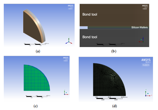
The thermo-mechanical wafer-to-wafer bonding process was modelled through a three-dimensional FE model. As a first approximation exploiting double symmetry, onequarter of the components inside the bonding chamber was considered in the FE model, see Figure 3a. Upper and lower wafers were constrained with a unilateral frictionless contact through two bond tools by which the mechanical constraints as well as the heat flux conditions were applied to the 8-inch silicon wafers; gf lines (with 3 mm length and 0.5 mm width) were placed at die borders, as shown in Figure 3b and 3c, respectively.

Figure 3. Finite element model of gf bonding: (a) one-quarter of the bonding chamber; (b) planar view of the FE model; (c) gf region; (d) FE model mesh.
4. Conclusions
This work focused on glass frit, a diffused bonding material in the MEMS industry. Experimental results were used to calibrate numerical simulations to estimate the effects of residual stresses arising during the thermo-compressive bonding. It was shown that:
The gf material was homogeneously deposited on the wafer since its effective elastic properties did not vary between wafer centre and periphery, as shown by the nanoindentation tests;
A rather large scattering of the nominal shear strength was observed in the shear tests due to the role of the defects; however, the crack path often involved the bulk silicon in the die, thus confirming the good bonding quality;
Stiffnesses and strength, as obtained from the shear tests, were adopted to model the gf layer during the thermo-compressive process via cohesive elements, allowing a three-dimensional numerical simulation; even with some simplifications (discussed at the end of Section 3.2), the comparison between simulated and observed out-of-plane displacements at the wafer surface appeared acceptable.