Introduction
Commonly for wet batch cleaning, Si3N4 is removed in a hot H3PO4 bath. This was used primarily for the removal of the local oxidation mask (LOCOS) that had SiO2 underneath it for a stress relieving layer. Selectivities of 40:1 were routinely obtained and that was sufficient for that process. Today shallow trench isolation is more commonly the application, where the Si3N4 layer is used as the CMP (chemical mechanical planarization) stopping layer. CMP is used to remove the topography of the wafer at this step and the Si3N4 layer must be removed after the process. SiO2 layers are exposed at this point and minimizing the SiO2 loss of these layers is critical. Consequently the etch rate of the SiO2 layers must be suppressed, raising selectivity of the Si3N4 to SiO2 etch rate. This has created a need for a high selectivity silicon nitride etch processes.
In current production, the Si3N4 is etched out in a hot H3PO4 bath. Due to the limitation of SiO2 budget on the product wafers, Si3N4 etching in hot H3PO4 intends to remove Si3N4 completely with minimal SiO2 loss, and therefore, a high selectivity is desirable. Both Si3N4 and SiO2 etching rates become lower and lower as production continues because of H3PO4’s decay. In our experimental tests, for example, both Si3N4 and SiO2 rates drop from 68 and 1.4 Å/minute to 40 and zero Å/minute, respectively, through the life of a H3PO4 bath, and consequently, the selectivity changes from 50:1 (= 68/1.4) to infinity (= 40/0) accordingly. Because SiO2 etching rate is small and the rate is the denominator in the selectivity calculation, a small drop in SiO2 etching rate substantially increases the selectivity value. Therefore, the control of a stable SiO2 etching rate is very important in order to maintain a stable selectivity. The SiO2 could change from an etching process to a deposition process, as the dissolved Si etching byproduct increases high enough in the bath. It was observed that the SiO2 deposition starts on local areas of the wafers as soon as the etching selectivity reaches 800:1. The end of bath life is determined by either too low Si3N4 etching rate or the beginning of SiO2 deposition, necessitating H3PO4 replacement.
Experimental Setup
Experimental testing was done in Akrion’s GAMA batch tool. The tool’s H3PO4 bath was filled with standard H3PO4 solution, made of 85% H3PO4 and 15% H2O in weight. (All concentrations of H3PO4 and H2O herein listed are weight%.) Its specific gravity is 1.69. The bath was equipped with coil cooling tubes above the chemical surface and was covered with a lid during the Si3N4 etching. The bath was heated up to a temperature and that temperature was maintained by a PID controlled heater. All of wafers were etched under the conditions of 165o C for 20 minutes followed by DI water rinsing and then by IPA vapor drying in other bathes, unless, their experimental conditions are specifically addressed in this article.
A NIR spectrometer was used to detect the water content. It detects water content by light absorption through the liquid. A DI water spiking apparatus was installed in the bath. The apparatus was spiking a certain amount of DI water routinely into the bath. for example, it spiked DI water for 14 seconds in every two-minute period, programmed in the tool’s parameter settings. The DI water spiking rate was fixed at 60ml/minute.

Fig1
200mm Si3N4 and SiO2 wafers were used. The Si3N4 wafers had 5 KÅ thickness of Si3N4 film on both sides and they were used for etching rate evaluations and for the simulation of product lots. One product lot equals 1500 Å Si3N4 removal on both sides of 50 of the wafers. The SiO2 wafers had 200Å SiO2 film on both sides. The Si3N4 and SiO2 films were measured with 49 points and 5 mm edge exclusion by a Rudolph S300 elipsometer. Its repeating error at one point is below 1.0 Å for the Si3N4 and below 0.5 Å for the SiO2. Chemical samples were collected from the bath at tests and the elemental Si concentration was analyzed by an ICP-MS (inductively coupled plasma mass spectrometry)
Results and Discussion
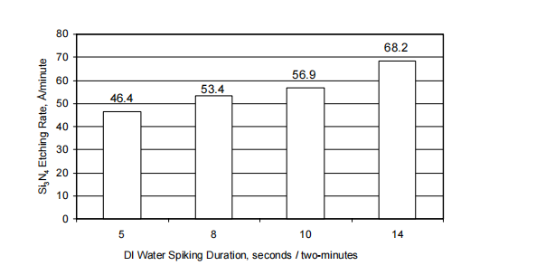
Water content impacts Si3N4 etching rate and the correlation is described in equation 1. Figure 1 shows Si3N4 etching rate with four durations of DI water spiking every twominutes. Each Si3N4 etching rate was evaluated after the water concentration was stabilized with the spiking. The figure shows the Si3N4 etching rates were 46.4, 53.4, 56.9 and 68.2 Å/minute for 5, 8, 10 and 14 seconds/two-minutes of the DI water spiking, respectively. Si3N4 etching rate was increased gradually with increase of the spiking duration. The spiked volumes were 5, 8, 10 and 14ml for the 5, 8, 10 and 14 seconds, respectively, because the DI water flow rate was at 60ml/minute.
Water content impacts SiO2 etching rate as well as Si3N4 etching rate. Figure 2 depicts both etching rates of Si3N4 and SiO2 with the change of water concentration in the same bath as for the tests shown in figure 1. The water concentrations of 3, 7.8, 10 and 14% in the bath were achieved with the spikes of 5, 8, 10 and 14 seconds per two-minutes, respectively. Figure 2(a) shows that Si3N4 etching rate was increased from 46.4 to 68.2 Å/minute with the change of water concentration from 3 to 14%, respectively. Figure 2(b) shows that SiO2 etching rate was decreased from 2.12 to 1.42 Å/minute with the change of water concentration from 3% to 14%, respectively.
上一篇: 先进的Pre-Gate清洁评估
下一篇: 硅晶片的酸刻蚀