1. Introduction
Transparent conductive oxide fifilms (TCO) have been comprehensively used in solar cells, touch panels, heat mirrors, organic electroluminescence devices (OLED) and liquid crystal displays (LCD) [1–3]. This is because TCO fifilms have wide band gaps, low specifific resistances and high transparencies in the visible and near infrared wavelength range. TCO fifilms are also key components for transparent electrodes in display and opto-electronic devices. Indium tin oxide (ITO), for example, has been commercially used in OLEDs. However, because of the cost and the scarcity of indium, researchers have been making effort to access other alternative materials for replacing ITO such as zinc oxide. It is a non-toxic, chemically stable, inexpensive and abundant material [4]. ZnO fifilms could be formed by electron-beam evaporation, chemical vapor deposition (CVD), pulsed laser deposition (PLD) and sputtering method [3]. Among these techniques, sputtering method offered much more advantages: it is safe and simply technique, performs high deposition rate at room temperature, emits non-toxic gas, and can be extended easily to large scale glass substrate. Therefore, most researchers used sputtering techniques to prepare ZnO fifilms [5].
2. Experimental
Zinc oxide fifilms were deposited on glass substrates by using 13.56 MHz radio frequency (RF) magnetron sputtering system. The ZnO targets were prepared from ZnO (purity, 99.99%) powder. The powder was mixed in a mechanical shaker for 24 h, pressed into a pellet 2 in. in diameters at high pressure, and then sintered at 1200 °C for 1 h in air. After pre-sputtering of the targets with Ar plasma for 5 min, ZnO fifilms were deposited on the substrates locating on a rotating sample stage at room temperature. Gases in the sputtering system were mainly consisted of high-purity Ar (99.99%). The glass substrates (glass slides of 76 mm ×26 mm × 1 mm) were cleaned in an ultrasonic cleaner for 5 min in acetone, alcohol and alkaline solution, and then rinsed in distilled water. All substrates were blown out by nitrogen gas. The structural and the electrical properties of the sputtered ZnO fifilms were characterized by X-ray diffraction (XRD),Field Emission-Scanning Electron Microscopy (FE-SEM), and atomic force microscopy (AFM), respectively.
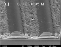
Upon increasing the concentration of C2H2O4 to 0.05 M, formation of ZnO fifilm, which cannot be observed for lower etchant concentrations, could be found on the fifilm surface, and the surface etching did not take place (Fig. 3a): the range of the C2H2O4 concentration for etching is limited, which can be regarded as a disadvantage of C2H2O4 etchant. Using FeCl3 ∙6H2O, etching of the subsurface regime could be found before the etching of the topmost layer was completed, resulting in formation of a porous surface structure.

Fig3a
Therefore, the etching rate increased under strong acidic environment. We measured pH of the etchants which are prepared with various mole concentrations. Fig. 5 shows the etching rate of the ZnO fifilms depending on pH of etchant. Previously, it was shown that the etching rate decreases exponentially with increasing pH value, and the etching rate depends only on the pH value regardless of a kind of etchant. In contrast to the previous results, the etching rate vs pH curve of FeCl3 ∙6H2O strongly deviates from the respective curves of the hitherto investigated etchants. For obtaining a better understanding of the reason of the dissimilar etching behaviors of FeCl3 ∙6- H2O compared to other etchants, further studies are required.
上一篇: 用氯化铵水溶液实现氧化锌薄膜的可控蚀刻
下一篇: 湿化学法控制ZnO纳米结构的研究