COMPLETE elimination of all possible impurities from semiconductor processing environments is very important for realizing ULSI devices of submicrometer to lower submicrometer feature sizes [l]. It is obvious that residual contaminants on wafer surfaces should be remarkably decreased with an accompanying increase in pattern densities. Because the particulate contamination on wafer surfaces mainly cause device failures, particlefree wet chemical processes are required for obtaining high yield and reliability for semiconductor fabrication. Generally, wet chemical processes can be classified as cleaning and/or etching processes using ultrapure water and chemicals and a drying process to remove water from wafer surfaces.
Wafer cleaning experiments were performed on artificially contaminated wafers. Polystyrene latex spheres having a diameter of 0.43 pm and silica latex spheres having a diameter of 0.5 pm were employed as organic and inorganic artificial particulate contaminants, respectively. Silicon wafers used for tests were 3-inches in diameter and ( 1, 0, 0) oriented p-type (6-8 Q-cm) or n-type (3-5 Q-cm). Latex suspensions containing 7 X lo9-7 x 10" particles/ml were diluted to lo3- lo4 particles/ml, and dropped onto the wafer surfaces, and then spun dry. By this procedure, wafers each having 500-2000 particles on its surface were prepared for cleaning tests.
The wafer surfaces were observed using a scanning electron microscope (SEM). Particle counts on wafers were evaluated using an Aeronca WIS- 100 wafer inspection system. The WIS-100 classifies defect sizes to particles (over 0.5 pm) and a so-called haze (below 0.5 pm). Before the experiments, the WIS- 100 was calibrated with a relative standard wafer.
Immersion time in each of the cleaning solutions is 10 min except for the dilute-HF solution. The time for immersion in dilute-HF is 1 min. After immersion into the solutions, the wafers were rinsed for 10 min in ultrapure water and then spun dry. Chemicals used in these tests are all of electronic grade and low particle levels [5]-[7]. The particle counts of'those over 0.5-pm diameter size in the chemicals were below 20 counts/ml or less. The quality of ultrapure water was 18.24 Ma-cm in resistivity, 5 ppb in total organic carbon (TOC), 2-3 ppb in silica concentration, and 0.3 count/ml in particle counts of those over 0.2-pm diameter size [8]. All equipment used for the wafer cleaning and rinsing were made of either TeflonPFA or quartz glass. The cleaning and rinsing processes were manually performed in a wet station.

Fig1
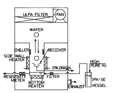
Fig. 1 shows a schematic diagram of the newly developed wafer drying system. This system consists of an IPA heating and chilling system, a wafer transport system, an IPA liquid delivery system, and a fan filter unit. The IPA liquid in the chamber is indirectly heated by the bottom heater. The evaporated IPA vapor is condensed by the chiller placed at the top inside of the chamber. Condensed IPA liquid is recycled. To make this system particle-generation free, all materials in the chamber in contact with IPA vapor and/or liquid such as the vaporizing chamber and the chiller were made of 316L stainless steel. All internal surfaces were precisely buffed by a mechanical polishing and a chemical treatment [9]. In the IPA delivery system, IPA liquid is fed from the stainless steel vessel through the Teflon membrane filter having pore size of 0.1 pm and then sent to the chamber. To avoid the particle generation from the tubes, the electro-polished 3 16L stainless steel tubes were employed. The wafer transport system is automatically operated in obedience to the sequences. To prevent particle contamination during wafer transport, the moving portions of the system are kept away from the wafers as far as possible. Clean air is passed through an ULPA filter and is streamed with the vertical and laminar flow to keep the high quality of cleanliness in wafer transport spaces.
Wafers which have diameters of 3, 4, and 5 in were cleaned with chemicals and ultrapure water as described above. After rinsing, the wafers were immersed into the vapor zone for 5 min. During the wafer drying operation, the wafers were set above the receiver in the vapor zone and any condensed IPA containing water was immediately taken out from the chamber through the receiver. After drying, the wafers were taken out from the chamber using the automatic transportation robot.
Comparison of Particle Removal Eficiency: Fig. 2 shows the particle removal efficiency of the five cleaning solutions for polystyrene latex spheres. The H2S04-H202 and the NH40H-H202 solutions with the low NH40H content were found to have a high removal efficiency for both organic particles and haze. The other cleaning solutions were also effective for removing particles. It should be noticed that only the NH40H-H202 solution of the standard ratio reported by Kern and Puotinen [2] showed an increase in haze formation. This is due to an irregular etching of wafer surfaces during cleaning as described later.
上一篇: 旋涂玻璃材料的旋涂及烘烤
下一篇: 玻璃晶圆机械性能:与硅的比较