In this study, a midsonic cleaning system for solar-cell wafers with a frequency of 750 kHz was designed and fabricated. Finite element analysis was used to design the system. The obtained peak admittance value was 750.0 kHz. Reflecting the analysis results, the system was fabricated and its admittance characteristic was measured. The measured data showed 753.1 kHz, a value that was consistent with the finite element method (FEM) result with 0.4% error. The acoustic pressure test was performed and the resulting pressures were found to range from 283% to 328%, with a standard deviations range from 36.8% to 39.2%. Then, the wafer damage test was performed, and no damage was observed. Finally, the particle-cleaning test was performed; when we applied 1100 W, 99.8% of particles were removed. These results indicate that the developed midsonic bath has the capability of cleaning effectively without inflicting wafer breakage.
Ultrasound has been widely applied in a variety of industries, such as in manufacturing, industrial cleaning and semiconductor wafer cleaning processes. Regarding manufacturing fields, Luo et al. and Jang et al. reported ultrasonic bonding process, and Ng et al. explained ultrasonic welding application. In addition, it can be used for micro hole machining, hot embossing, burnishing polishing and nano-surface reformation process. In our previous works, ultrasonic waveguides for semiconductor wafer cleaning apparatus are included. Some researches are reported about megasonic cleaning mechanisms.
In this research, we have used ultrasound for a solar-cell wafer cleaning system. Recently, solar energy has attracted attention as a promising clean energy source in the future, and solar energy generating systems are being widely developed. The major energy converting photovoltaic parts are fabricated on solar cell wafers, and as a result the demands on manufacturing solar cell wafers have been rapidly increasing.
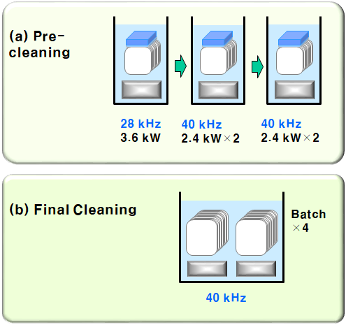
The detailed recipes for the cleaning process are as follows. In the pre-cleaning process, 28 kHz, 40 kHz, and 40 kHz ultrasonic cleaning processes are involved in a sequence. For the second and final cleaning, 40 kHz ultrasonic with full power up to 900 W is used. In this process, due to the wafer breakage problem, the use of 250 W power is recommended. The cleaning recipes are illustrated in Fig. 1.
In this article, a midsonic cleaning system with a frequency of 750 kHz in the midsonic range between 100 kHz and 1 MHz is designed and fabricated. Finite element analysis was used to design the actuator and the stainless steel plate. Then, performance tests are processed in the point of acoustic pressure output and the wafer cleaning efficiency with the breakage test. Finally, the results are compared with those of a conventional type, and the performance is discussed.
To design the ultrasonic system, finite element analysis was performed using commercial FEM tool ANSYS software. First, in order to design the actuator, it was modelled two-dimensionally as an axis-symmetric rectangular shape. The material of the actuator was piezoelectric ceramic, and the properties were given to the model. For actuation, electricity should be supplied, the top line and the bottom line were used as electrodes for the analysis. They were electrically coupled to each other, and 1 V was applied to the top while 0 V was applied to the bottom line as a ground. The calculations were done by changing the frequencies from 600.0 kHz to 900.0 kHz. The obtained admittance graph is shown in Fig. 3(a), and the peak admittance value was 750.0 kHz. Based on the analysis dimensions, a real piezoelectric ceramic actuator was fabricated, and the top and bottom surfaces were coated as electrodes. In order to make it easier to connect wires, the bottom electrode was drawn to the left lower corner of the top electrode. Subsequently, the admittance characteristic of the piezoelectric ceramic actuator was measured and plotted in Fig. 3(b). The peak value was 749.0 kHz, which was consistent with the previous analysis value. Thus, the value of 750.0 kHz was chosen as the design frequency of the system. The fabricated piezoelectric ceramic actuator (137 × 39 × 3 mm, a thin rectangular type) is shown in Fig. 4.

Fig1
After fabricating the ultrasonic bath, the acoustic pressure distributions were measured over the plate filled with water. The experimental setup is composed of a hydrophone sensor (Ø 2.5 × 70.0 mm, Onda corp.) attached on the jig, three-axis moving columns and a computer analysis system, as shown in Fig. 7. When measuring the data, the sensor is moving in a zig-zag path with 0.05 mm steps so that it can scan the desired area in detail. The measured data is transported to the computer and the pressure distributions are displayed in real time. After saving the data file, it is analyzed by calculating the maximum values and standard deviation values.
上一篇: 薄膜有机光伏电池中使用微透镜捕获光
下一篇: 强化化学清洗工艺的处理槽腐蚀研究