The definition of a supercritical fluid can be fully appreciated by examining a phase diagram such as the one for CO, in Fig. 2. The key property is that above the critical temperature (T,) condensation cannot occur at any pressure. The region to the right of T, and above P, defines the supercritical state. A supercritical fluid can have very high density.
Supercritical CO, was chosen as a primary cleaning fluid for its low viscosity (0.05 centipoise), high diffusivity, and very low surface tension, as well as other environmental, safety, and cost considerations (Table I). For CO,, the critical temperature, T,, is 31 "C and the critical pressure is also in a practical range (Pc = 73 bar = 1050 psi).
Figure 3 shows density versus pressure for an isotherm just above the critical temperature. Density changes dramatically with pressure near the critical point. At 31 "C, for example, the density is only 0.002 g/cm3 at ambient pressure, compared to 0.468 g/cm3 at Pc (a 234-fold increase!).
CO, above Pc has a density and solvating capabilities comparable to organic liquids. The solvent strength of CO, varies with pressure for a constant temperature. Physicochemical properties can be exploited both above and below Pc, i.e., supercritical and subcritical properties are both important in a well-designed cleaning process. In such a process, the fluid is cycled between two pressures as indicated in Fig. 3.
A wafer cleaning system that uses CO, in the critical region has recently been introduced. As shown in Fig. 4, the wafer is loaded between the upper and lower blocks of the cleaning chamber. The chamber height is about 5 mm during loading, and the wafer is held therein by vacuum grips in the top block. The lower block is then raised until the chamber is sealed, at which point the chamber height is only slightly larger than the wafer thickness (- 1 mm). CO, pressurized at - 800 psi is then supplied through centrally positioned orifices.
During the cleaning cycle, the supercritical fluid is pulsated by a hydraulic mechanism. The lower chamber block is actually a thinwalled, stainless steel membrane, i.e., a diaphragm. The hydraulic fluid pressure changes the chamber height via elastic deformation of the diaphragm, i.e., the supercritical fluid pressure is varied according to the volume of the cleaning chamber. Pressure is typically cycled between 800 and 1200 psi at a frequency of 25 to 50 Hz.

Fig1
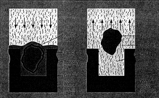
During the expansion stroke, the CO, changes kom a supercritical fluid to a subcritical gas. Density decreases threefold, causing rapid mixing actions and outflow of fluid from the wafer surfaces. The fluid, moving at high velocities, quickly relocates suspended particles and dissolved contaminants. These are flushed out of the chamber by makeup cleaning fluid during the expulsion step. Redeposition is prevented by the rapidity of fluid flow throughout the process.
The lower cleaning gap is very small (< 30 pm) . As a result, the wafer follows the reciprocating movement of the lower chamber block. A hydraulically actuated pulsator in the central section drives the lower chamber block. This provides an optimal wafer cleaning action in both the upper and lower wafer clean gaps. The total fluid volume surrounding all sides of the wafer is only about 5 cm3 (= n r2 h = n 20 x 20 x 0.0125 cm3) in the uncoinpressed (800 psi) position. This low cleaning fluid requirement simplifies control of fluid purity.
The fluid properties and chamber design are such that the pressure varies little from the top to bottom surfaces of the wafers. At any given time, even during the strokes, an essentially uniform pressure distribution exists in the chamber. The wafer is totally surrounded by the cleaning fluid during the cleaning process. Thus the wafer is not physically stressed by the thrusts or pressure changes of the cleaning fluid.
下一篇: 晶圆清洗:湿法仍然领先